Utility Requirements for Bubble Film Extrusion Machine Installation: Water, Air, and Power
2026-05-18
Integrating high-performance bubble film extrusion lines into a continuous 24/7 production environment requires precise alignment with plant infrastructure. Mismatches between utility supply and equipment demands directly cause thermal lags, pneumatic drops, and thickness variation.
Proper setup of electrical, pneumatic, and cooling systems ensures optimal film quality, melt consistency, and uninterrupted extrusion line speed.
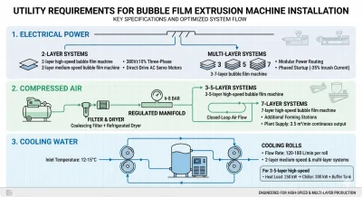
1. Electrical Power Specifications and Stability
Stable electrical architecture prevents voltage drops during high-torque extruder startups and eliminates polymer melt inconsistencies.
2-Layer Bubble Film Systems
- Voltage Requirement: A stable 380V±10% three-phase supply is mandatory for both the 2-layer high-speed bubble film machine and the 2-layer medium-speed bubble film machine.
- Drive System: Engineered with direct-drive AC servo motors to maintain consistent extrusion torque.
Multi-Layer Co-Extrusion Systems
- Power Architecture: The 3–7-layer bubble film machine utilize modular power routing.
- Inrush Reduction: This design allows a phased startup of individual extruders, reducing peak inrush current by 35% compared to simultaneous ignition.
2. Compressed Air and Pneumatic System Requirements
The vacuum forming section relies heavily on balanced pneumatic pressure to guarantee uniform bubble geometry and prevent film ruptures.
Air Flow and Pressure Control
- Regulated Pressure: The 3–5-layer high-speed bubble film machine features a closed-loop compressed air manifold feeding the forming section at a constant 6–8 bar.
- Air Contamination Control: The pneumatic circuit requires an inline coalescing filter and a refrigerated air dryer. Eliminating oil and moisture carryover prevents vacuum hole clogging and bubble rupture.
- High-Capacity Demands: For the 7-layer high-speed bubble film machine, additional forming stations increase total air consumption by 40%. A plant air supply with a continuous output of 3.5 m³/min is required to maintain a 98% vacuum seal success rate.
3. Closed-Loop Cooling Water and Chiller Requirements
Efficient heat removal is critical for rapid bubble film solidification, gauge thickness control, and preventing sticky film surfaces.
- Flow Rate: The 2-layer medium-speed bubble film machine and all multi-layer systems require a dedicated closed-loop chilled water circuit. This circuit must deliver 120–180 L/min per cooling roll.
- Inlet Temperature: The water temperature must remain regulated at 12–15°C to efficiently extract the latent heat from the molten polymer.
- Chiller Sizing: For the 3–5-layer high-speed bubble film machine, the extrusion process generates a heat load of up to 250 kW. An industrial chiller with a minimum capacity of 300 kW and a dedicated buffer tank is recommended to prevent residual heat buildup.
4. Operational Impacts of Utility Infrastructure
| Utility Deficiency | Direct Technical Consequence | Impact on Production Line |
|---|---|---|
| Undersized Electrical/Cooling | Thermal shutdowns, uneven bubble walls | 20% reduction in line speed within 30 days |
| Optimized Utilities (Verified) | Uniform melt consistency, steady vacuum seals | Over 96% first-pass yield rate from startup Proper technical preparation protects the mechanical integrity of the extrusion line. Verifying voltage stability, compressed air filtration, and cooling water conductivity ensures maximum equipment uptime, precise thickness control, and continuous high-speed production output. |